


Easy Project Power Supply For Raspberry Pi & Beaglebone
Easy Project Power Supply For Raspberry Pi & Beaglebone
DC to DC 4.5-30V to 1-30V 12A Buck Converter Step Down ReviewI'm often building projects with Raspberry Pi or Arduino and somtimes I need to power some external equipment too. Recently I designed a product that used a Raspberry Pi needing 5V, two Arduinos requiring 5 - 12V and a 7 inch touch screen that runs from 12V. I had to come up with a simple way to provide both 12V and 5V for the unit. The situation could have been worse though. I might have designed in a 3.3V Arduino and used something else that runs from 9v. Clearly I only wanted one wall plug to plug it all into so how can you generate all the voltages that you need? The touch screen needed 12 volts so it made sense to get a 12 volt power supply to start with and I would generate all the other voltages needed by the system from it somehow. The Arduinos can be run from 5V which is the same voltage needed for the Raspberry Pi. All I had to do was convert the 12 volt input to 5 volt. Linear power suppliesMy first thought was to use a linear power supply to drop the voltage from 12 to 5 at a maximum current of around one Amp. This would work but it would also get very hot and waste a lot of power. The linear supply would need to drop 7 volts while delivering 1 Amp to the load. You can calculate the power that the supply would need to generate using the equation P = IV where P = power, I = current and V = voltage. In this case P = 1 * 7 = 7 Watts. Switch mode power suppliesI started to look at switched-mode or Buck converters to do the conversion from 12V to 5V instead. A switched mode converter works by switching the input supply on and off at high frequency and filtering the output to make it a steady voltage again at the output. The voltage at the output is controlled by the ratio of the on to off switch times. The longer the input is switched on the higher the output voltage. So how does all this help the power dissipation problem? Well, as you saw above, the power is calculated by multiplying the voltage by the current. The linear regulator example delivered 1 Amp while dropping 7 volts so the power dissipated was 7 Watts. A switched mode power supply on the other hand is either on or off so when it is off there is no current flowing and when it is on there is no voltage across the switch. The theoretical result of this is that there is no power dissipation. I say 'theoretical' because no circuits are perfect and there will be some power dissipated in practice. It will however be small change compared to the linear approach.
3A Buck converter solved my problemI estimated that my Raspberry Pi, the two Arduino Unos and all the sensors that they were attached to would draw less than one Amp so I used a Buck converter module like the one pictured above to step down from 12V to 5V. It works perfectly and it hardly gets warm at all. The unit I used will work with an input voltage from 3V to 40V and provided that the input is higher than the required output, it will provide a supply anywhere from 1,5V to 35V. It is rated at 3A maximum current but as a precaution, I would not plan to supply more than 2A with it. Even at 2A you may need to consider some heat sinking but it hardly got warm at all in my circit. Warning: Make sure that you set the correct output voltage firstBefore connecting it to the Raspberry Pi and other equipment that you want to power from it. Connect a voltmeter to the output and adjust the trimpot to the desired output voltage. 12A Buck converter For Your next projectThe module pictured at the top of this article is a Buck converter similar to the tiny 3A unit. The difference is that this module is rated at 12A which allows for more possibilities. I plan to use one of these to build a general purpose unit to power my development projects but I will only plan to use it up to 5 Amp to avoid allowing the module to heat excessively.
Before using the Buck converter I wanted to make sure that it would deliver the current that it claimed. This proved a little more difficult than I had anticipated. The only low ohm power resistors I had in my junk box were 6.8Ω 3W devices. Connecting one of these across the output of the converter at 5V draws a current of approximately 0.75A and generates 3.75W of power dissipated in the resistor. After a few seconds the resistor begins to smoke so I can only do this test for short periods. I had a limited supply of these resistors but I managed to find 8 of them. I twisted the component leads together as in the picture and connected them all across the output with an Ammeter connected in series. I turned on the power and measured a little over 5 Amps. I left it running for as long as I could which was just before the load resistors burst into flames. The heat sinks on the Buck converter were only just starting to get warm which leads me to think that this device will serve my purpose well. These DC-DC converters are not expensive so why not try out the 3A Buck converter or the 12A Buck converter for yourself. Easy Project Power Supply For Raspberry Pi & Beaglebone |
| Now subscribe to our newsletter and don't miss a thing |
|
|

 Inexpensive 12 Amp step down DC-DC converter
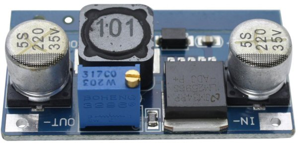 Inexpensive 3 Amp step down DC-DC converter
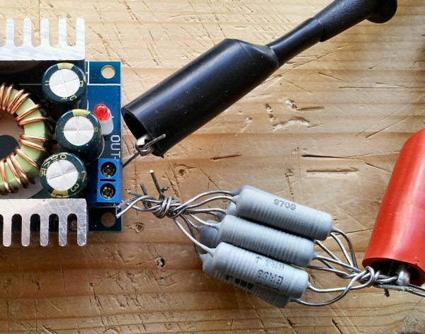 Makeshift 5 Amp load
You should assume that there is an affiliate relationship and/or another material connection to the providers of goods and services linked to on this page and that we may be compensated when you purchase from a provider. Homediyelectronics.com is a participant in the Amazon Services LLC Associates Program and the Amazon EU Associates Programme, an affiliate advertising program designed to provide a means for sites to earn advertising fees by advertising and linking to amazon.com and amazon.co.uk.
Copyright © 2013 - 2026 homediyelectronics.com |
Legal |
Contact me |
Feed |
Google |
Site Map
Comments
No comments yet.Add Comment