Sound Card Oscilloscope traces - Arduino to Servo
 Servo drive signal 1-2ms pulses every 20ms
The Arduino 'Servo' library produces a pulse width modulated position demand signal to the servo motor. The width of the pulse is approximately 1-2ms depending on position and the pulse repeats every 20ms. The first trace on this page shows the output signal as displayed on a Sound Card Oscilloscope.
I chose to use a Sound Card Oscilloscope to capture the signals partly to show how surprisingly effective such a tool can be considering the tiny cost required to build one but also because it was more convenient than using my big scope.
Do not use the Sound Card Oscilloscope on any device that is also connected to your PC.
When I tried this without thinking because I had just loaded the sketch through the USB I got some very weird results that confused me for a while until I realised what I had done. So, when you have loaded the sketch onto your Arduino, disconnect it from your PC and connect it to an alternative power source. I used a 'Power Bank' 5v battery connected to the USB which worked well but you could use a wall plug supply into the 7-12v input if that's more convenient for you.
I could have used screenshots from my conventional 100MHz oscilloscope which would have shown the signals to be much cleaner and distortion free but it would not have added significantly to this discussion. It was also far more convenient to use my PC to observe these signals. Provided you remember it's limitations you can use it effectively.
Some of the trace images on this page have been enhanced to make them easier to view and to remove the graticule. In most cases we are more interested in the shape, width and repetition rate of the signals than we are of making absolute measurements.
Servo signal trace explained
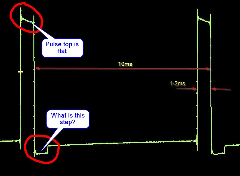 Annotated drive signal
The above trace shows the timings of the pulse and I've ringed a couple of points of interest. If you were to use a high bandwidth, DC coupled scope to view this signal then you would see that the top of the pulses are flat and horizontal. The Sound Card Oscilloscope is AC coupled however. This means that any steady voltage will be seen to decay towards zero and you can see this decay as a slope on the top of the pulse. This is normal for the SCO.
I've also ringed an unexpected artifact on the trace. At least I was not expecting it. I will explain what this is later.
The servo measures the pulse width then drives the motor
What is going on inside the servo? I don't have a diagram for the circuitry inside the servo but we can make a few assumptions about how it works.
The first thing that must happen inside the servo is to measure the width of the control pulse and it can only do that after the complete pulse has been delivered. The demand signal is then compared against the motor shaft position signal from the potentiometer to produce an error signal which then drives the motor in the appropriate direction. Refer to the diagram here
What is that little step on the trace after the control pulse?
 Servo drive signal and the 5v line
I should tell you that the pulse traces above were observed from my test circuit before I added the 4700µF capacitor across the 5v supply. I didn't put it in initially because I was following the Sweep circuit on the Arduino site
When I went in search of the cause of the step on the trace I suspected that it might have something to do with the motor being turned on at that point. An examination of the 5v power line confirmed this. The +5v supply voltage is plotted in the red trace.
Now I expected to see something happen on the 5v line when the motor activates because it does need a lot of current to drive it. I wasn't expecting to see that the 5v line was pulled down by almost 1.5v however. This was much more serious than I thought and it's a wonder that the microcontroller doesn't reset under these conditions. It's only the fact that the Atmega328 has a wide supply voltage tolerance which saves it from disaster.
Connect a 4700µF capacitor across the +5v power supply
 With 4700µF Capacitor
To minimise the ripple on the 5v power rail connect a large electrolytic capacitor between 0v an +5v. Make sure that the working voltage of the capacitor is 10v or above and that you connect it the correct way around with the '+ve' lead to the +5v.
This provides a smoothing effect and averages out the disruption to the +5v supply voltage. While it doesn't eliminate it altogether, it does greatly reduce the strange step that was observed on the signal line following the control pulse. You could try out any value capacitor to see what effect it has. I used a 4700µF Capacitor because I happened to have some in my junk box.
If you are going to use larger more powerful servos or you intend to drive a lot of them you would do well to provide the servos with their own power supply. This will avoid any problems with the digital electronics resulting from the high current pulses which occur when motors are driven.
Now that you know how servo motors work you should be able to build systems to control them whenever you need to. When you do you will find the design process is much easier with an oscilloscope at your disposable even if it's only a Sound Card Oscilloscope.
| 


Comments
No comments yet.Add Comment