

Simple Transistor As An Amplifier
A very stable amplifier when designed correctly
A simple transistor amplifier circuit can be used for many things including an audio preamplifier to amplify small signals before passing to filters or a power amplifier. 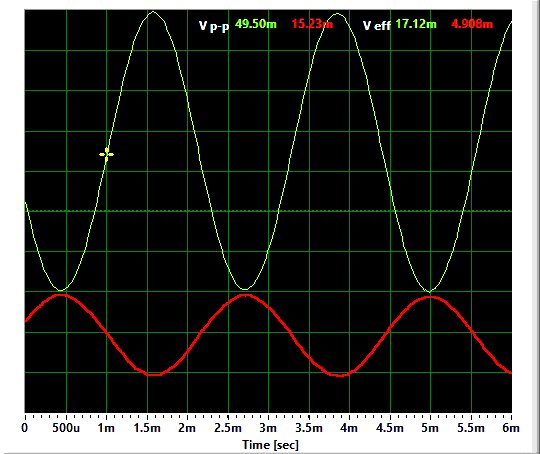
Despite the fact that this circuit consists of only five components it can deliver significant gain while remaining very stable over a wide temperature range. The reason for this stability is the resistor R2 which provides negative feedback from output to input. One of the objectives of the design of this circuit is to set the output voltage Vo to approximately half way between the negative and positive supply voltages when there is no input signal applied. When that is achieved the output is free to swing equally from almost zero to the full positive voltage providing a large undistorted output signal. The problem is that the output voltage level is dependant on the gain of the transistor and this can vary widely from device to device. The difficulty of matching individual transistors with gain within a certain range may be why the circuit is not often used in commercial, mass produced products. However, providing that you design your amplifier circuit around the devices you use there is no problem with using it in your hobby projects. 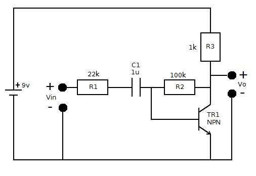
The components in the circuit above were chosen to provide a good output level with a transistor gain or β of between 50 and 180 and still produce an output amplitude of at least 4V. A general purpose NPN bipolar junction transistor such as the BC547 should be adequate. You may need to adjust the value of R2 if the signal is distorted. The capacitor C1 provides DC blocking to ensure that if there are any steady voltages on the input they will not upset the biasing of the amplifier. The oscilloscope traces in the image at the start of this article show the input and output waveforms on the same scale. The input was set at 1V peak to peak which produced an output of approximately 3.7V. This is a gain of 3.7 which is a little lower than the 4.5 value suggested by dividing R2 by R1. I used my sound card oscilloscope to generate the input signal and to observe the input and output waveforms. I also used it to calibrate the input of the oscilloscope to 500mV per division. As I said earlier, you have to design this circuit around each individual transistor for best results and you have to make sure that your output is not distorted like the output below. 
Do you see how the bottom of the sine wave has flattened off? That's due to the bias current of the transistor being too high and restricting the negative voltage swing. I produced this waveform by reducing the values of R1 and R2 to increase the base bias current while keeping the gain constant. If your circuit produces an output waveform that clips at the top or bottom then adjust the values of R1 and R2 to correct the problem. |
| Now subscribe to our newsletter and don't miss a thing |
|
|

You should assume that there is an affiliate relationship and/or another material connection to the providers of goods and services linked to on this page and that we may be compensated when you purchase from a provider. Homediyelectronics.com is a participant in the Amazon Services LLC Associates Program and the Amazon EU Associates Programme, an affiliate advertising program designed to provide a means for sites to earn advertising fees by advertising and linking to amazon.com and amazon.co.uk.
Copyright © 2013 - 2024 homediyelectronics.com |
Legal |
Contact me |
Feed |
Google |
Site Map
Comments (2)
Could you also tell us how to calculate the resistance required according to our transistor?
Lets say I bought my own transistor from a nearby shop and I know the collector-emitter voltage, ..... all the specs of the transistor I have, how do I calculate the resistance that I need to use for the transistor?
Add Comment