


Power Off Delay Circuit
<< Previous
First
2
3
4
Last
Next >>
Automatic Power Off Shutdown For Raspberry Pi Power Off Delay Circuit Relay Driver Circuit Power Failure Detection Circuit DCDC Buck Converter
Power off delay circuit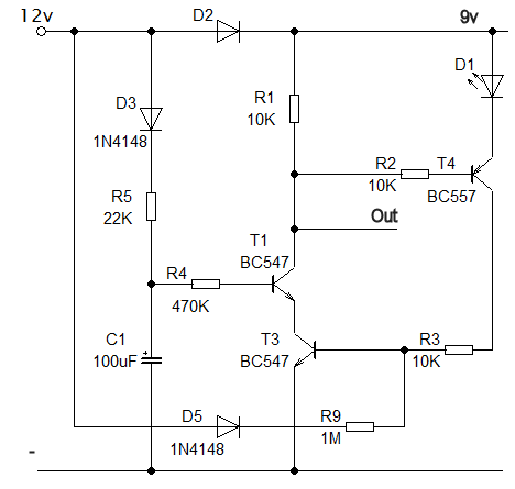 Power fail delay circuit
How to build a long time delayThe diagram shows a simplified version of the delay part of the circuit. 12 volts is supplied by a mains powered supply where it powers the computer through D2 and charges capacitor C1 through resistor R5. When the 12V supply is removed C1 discharges through R4. The delayThe delay depends on the time it takes for C1 to discharge. In order to achieve the longest delay possible I wanted to make sure that the switching point is as low as possible because it's the voltage on C1 that determines the end of the delay. The circuit I came up with provides a threshold voltage of just 0.8V made up by transistors T1 and T3. This is achieved by using transistor T3 in place of a resistor which is often found in switching circuits. When it is fully charged C1 has a voltage of 11.4V. When the 12V supply is removed the voltage on C1 begins to decay through R4. When the voltage decays by 10.6V it will reach 0.8V and the circuit switches to indicate the end of the delay. The delay time is therefore the time it takes C1 to discharge by 93% The time constant of an RC circuit is found by multiplying the two values together. This gives a time in seconds, that it takes to discharge to 0.37 of it's fully charged voltage. The time constant in this case is: t = 470000 * 0.0001 = 47 seconds. So if the voltage starts at 10.4V then after one time constant the voltage is: 3.8V. After 2 time constants the voltage is: 1.4V and after three time constants it will be 0.52V. The circuit should switch some time between 2 and 3 time constants or 94s (1:34) and 141s (2:21). My Raspberry Pi takes roughly 12 seconds to shutdown so this delay is going to be more than adequate. I can reduce the capacitor value to speed up the power off if it turns out to be far too long. The switching circuitWhen the voltage on C1 passes through the switch threshold point it is changing very slowly. If this signal is to be used to switch a relay then it needs to be converted into a clean transition between off and on. This is accomplished by the Schmidt-trigger type circuit made up of T1, T3 and T4. When the 12V supply is present T1 and T3 are held on. When the power is removed and the C1 voltage drops to approximately 0.8V T1 begins to turn off and the voltage on it's collector begins to climb. Eventually T4 starts to turn off which starves T3 of base current which sends T1 collector even higher. This process all results in the output of the circuit switching quickly between on and off. The diode D5 and resistor R9 are there to ensure that T3 turns on when the main 12V supply is applied. D5 ensures that the connection is removed when the 12V supply fails. LED D1 is there to provide a voltage drop of around 3V which will ensure that T4 turns off at about 3.6V below the 9V supply voltage. Remember that this will only happen when the 12V supply has vanished. D1 also makes a handy ON indicator as it is illuminated whenever there is a supply to the computer.
<< Previous
First
2
3
4
Last
Next >>
Automatic Power Off Shutdown For Raspberry Pi Power Off Delay Circuit Relay Driver Circuit Power Failure Detection Circuit DCDC Buck Converter |
| Now subscribe to our newsletter and don't miss a thing |
|
|

You should assume that there is an affiliate relationship and/or another material connection to the providers of goods and services linked to on this page and that we may be compensated when you purchase from a provider. Homediyelectronics.com is a participant in the Amazon Services LLC Associates Program and the Amazon EU Associates Programme, an affiliate advertising program designed to provide a means for sites to earn advertising fees by advertising and linking to amazon.com and amazon.co.uk.
Copyright © 2013 - 2024 homediyelectronics.com |
Legal |
Contact me |
Feed |
Google |
Site Map
Comments (1)
Add Comment