|
How to modify the Arduino Pro-Mini for Ultra Low power 5µA sleep mode
An unmdified Arduino Pro-Mini microcontroller only requires 20mA when running at full speed with a 5v power supply. This is not much but if you only have a small battery with a 160mAh capacity then at best you can only expect it to run for a few hours. The object of this exercise is to run the board for months not hours so how do we do it?
Which Pro-Mini 5v or 3.3v?
There are two versions of the Pro-Mini board. The 5v version runs at 16MHz and draws 20mA while active. The 3.3v version runs at 8MHz and needs less than 5mA in active mode. The 8mHz board runs slower but it will be plenty fast enough for a lot of applications. The saving in power consumption makes it the obvious choice for this exercise.
Saving more power
There are three simple things you can do that will save significant amounts of power. Two of them are hardware and one tweak to the Arduino IDE.
- Disconnect Power On LED
- Remove Voltage regulator
- Disable Brown Out Detector (BOD)
Inspiration for these modifications was taken from the article How To Run ATmega328P For a Year On Coin Cell Battery
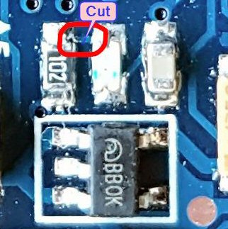
Remove or disconnect the Power On LED
LEDs use very little power compared with the old filament light bulbs that came before them but even 1mA used to power the LED would limit the life of a button cell to less than a week. So it needs to go.
The Power LED is located between the cpu chip and the regulator as shown in the image to the right. If you power up the board you will see it glow.
You can either remove the LED with a soldering iron and a steady hand or you can cut the track with a sharp knife or scalpel which is what I did.
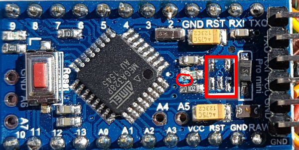
Remove the voltage regulator
The voltage regulator doesn't waste as much power as the LED but it isn't going to be used for the icicle application so it might as well go. The easiest thing to do is to remove it with a small soldering iron. Be careful not to make any solder bridges.
The image below shows the modified board with the LED track cut and the regulator removed.
Disable the Brown Out Detector circuit BOD
The BOD circuit is integrated into the ATMega chip. It detects when the Vcc voltage falls below a threshold and holds the cpu reset until Vcc recovers. Its purpose is to protect the system in the event of short power failures or 'Brown outs'.
The BOD circuit needs a small amount of energy to function and it also resets the cpu before it stops working because the battery voltage is too low. The button cell will last longer if the BOD is disabled.
I found that the best way to disable the BOD circuit was to re-program the fuses on the chip. This can be done by editing the boards.txt file in the Arduino IDE then burning the bootloader which also programs the fuses. The Pro-Mini doesn't have a USB interface so the easiest way to program it is with the ICSP connector. This is in fact the only way to program the fuses and bootloader.
Programming the Pro-Mini fuses and bootloader is simple using an Arduino UNO as an ISP shown here: Arduino Pro-Mini ISP Programmer UNO. I made a shield to carry a Pro-Mini for programming. This provides an easy way to program the Pro-Mini away from its application hardware.
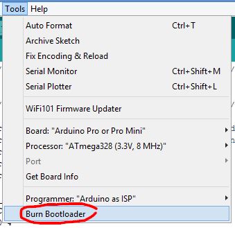
First edit the boards.txt file in the Arduino IDE. This file is located in the \hardware\arduino\avr folder. Change the value for the extened fuses in the 'Pro or Pro Mini (3.3V, 8 MHz) w/ ATmega328' section of the file.
Then change the fuse settings on the Pro-Mini board by using the 'Burn Bootloader' option from the 'Tools' menu of the Arduino IDE.
Ok by now your Pro-Mini board should require less than 5µA while in power down sleep mode. Now you can build a Christmas icicle decoration starting with the board to accommodate the Pro-Mini.
| 


Comments (2)
Add Comment